
I don't know if this is the right catagory to discuss projects in the works, but here goes anyway...
Background:
You've seen me fly Slipstick IV or "The Twins" (Micky and Ricky), a two stage 3" dia rocket that is 11 feet long weighing in at 15 lbs, which was designed to use two K700's in sequential staging. I wasn't quite comfortable with the length of the Twins, as it is a bit long and ungainly after you include 4 avionics bays and three deployment systems. I wanted to see if I could make everything a lot shorter by moving the 1st stage to the sides, like pods, but not have to worry about pod ejection, which isn't really a multiple stage, as far as having separate sequential staged rockets. Additonally, the pods generally use single deployment and can be scattered far apart from each other.
Solution:
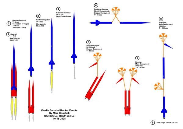
A "Cradle Boosted Rocket" (tm). You heard the term first used here. It basically involves a pod-like arrangment for the booster, where two or more pods are all attached together around a central "Cradle" as part of a cluster, with the sustainer, mounted above and in-between the pods resting on the cradle. The benifit is that the cradle is a totally separate one-piece rocket section and the sustainer, once separated from the booster does not carry any extra weight. The Cradle Booster can utilize dual deployment as one pod handles the drogue, and the other the main chute. See the following flight sequence:
Design:
Slipstick V (Trident would be a good name for this, but its a bit over used, so maybe Twin-Trident?) in its present form consist of three 54mm in-line airframes, made from Performance Rocketry Little Dog Dual Deploy Kits (and extra parts). It is designed for three minimum diameter K motors (K700's or K660's), but it has 38mm options as well. The sustainer's motor extends out the bottom of the sustainer and is used as the coupler into the cradle. The motors are retained in the airframe at the forward closure end. Avionics are mounted in the nose cones of the Cradle pods (deployment) and in the center cradle airframe (sustainer ignition timer). The sustainer has a conventional avabay in the mid section for dual deployment and a DC20 (GPS) in the nose cone. Estimated altitude goal is to bust 30K.
I've had a few revisions to the design, based on availability of components, but here's the latest drawing (showing conical nose cones and 3 fins on the sustainer instead of 4)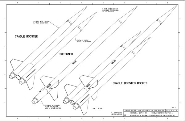
Download all pages of the mechanical drawing here:
http://www.telerover.com/rockets/CR/ENGINEER_CRADLE_ROCKET_54X54_V3_R5.pdf
Application:
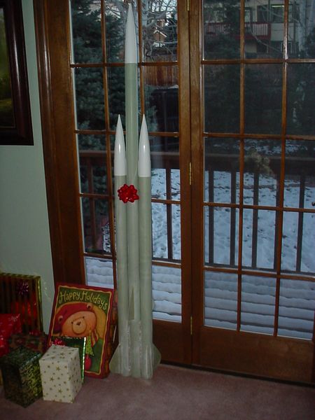
I received the three kits from Wildman Rocketry (two days ago) with a Christmas discount so they ended up costing a total of $238 (w/shipping) for all three. This was my present from Becky so, although she let me get a head start on it (mounting the fins and cradle) I had to put it with the other presents for Christmas day. 😆 You'll noticed a put radii on the fin tips for my 'signature look' although one picture still shows them as a trapezodial.

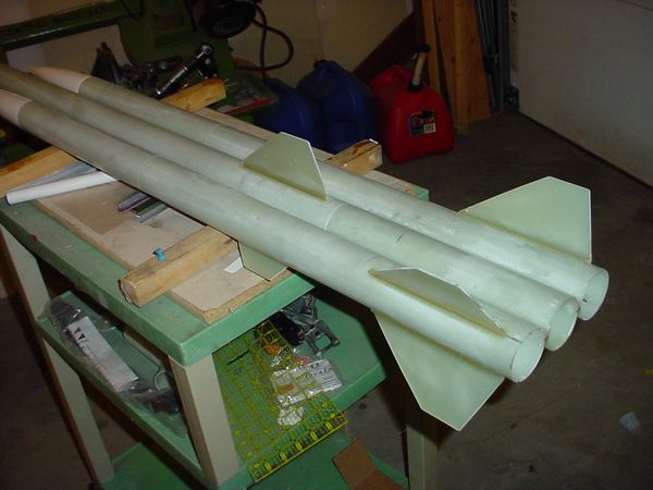
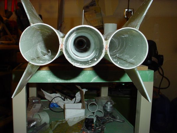
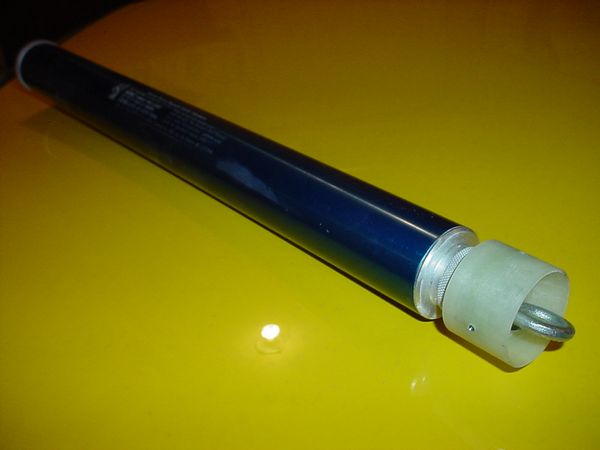
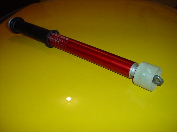
I'll add some FG and CF cloth to the fins and pods to reinforce them next week and build the avbays. As was mentioned, Motors are restrained at the forward closure. There is a moveable bulkhead that can be adjusted for different motor lengths, and is held in with three (Booster pods) or four (sustainer) 6-32 screws, removable from the outside. Here's a 54mm and 38mm motors to show the flexibility.
That's all for now. If I could get my RRC2-minis back from a refresh at Missileworks, I could probably push to try and fly it on Jan 3rd, but for now I will probably do a scaled down version using BP motors, just for grins. 😉 If anyone want to take a peek at it I can bring it to the annual January meeting
That really looks cool. I want to start getting into multi-stage rockets this year. Bring it to the meeting, I would love to see it and ask you tons of questions 🙂
Way cool, Mike. I love it. Kind of like a launch-able tower.
Was the motor retention your own scratch design, or was it part of a kit?
Was the motor retention your own scratch design, or was it part of a kit?
Thanks, guys. This retention methode was my idea, as there was no room at the rear for the typical Aeropack retainers, plus the sustainer has a flush aft closure so there is nothing at that end to hold on to. I could epoxy a bulkhead in place, but 1) I would be stuck with one motor length and 2) There would be no way to get to the forward closure if the eye bolt did not loosen from the motor hardware.
These can be easily made by anyone, and uses 6-32 T-nuts epoxied into place... but I think a 1/4" thick aluminum disk drilled and tapped for various screw patterns would offer more flexibility, and could be marketable.
I'm putting my build sequence up on http://www.telerover.com , if you need more details.
Great idea Mike. Can't wait to see it fly. Hold off until warmer weather would 'ya? Given the current weather forecast, I don't think 1/3 is going to happen for me.
Warren
Given the current weather forecast, I don't think 1/3 is going to happen for me.
Warren
? The launch is still 10 days away, what weather forecast are you looking at? Stop using the weather as an excuse Warren, come to a launch. Just got to give you some crap. 😉 Merry Christmas!
Mike,
I'm sure you have a novel answer for this, and I hope to hear it soon, but how are you going to light the sustainer? With the motor being the coupler to the cradle, there's no room to run leads down from the sustainer av-bay, and if you light it from the cradle, you can't have a separation-coast-ignition sequence like you did with the Twins. I've been trying to think of some ideas, but nothing short of head-end ignition front closure comes to mind. 😈
Anyways, cool project. I'll be working on my Comp3, but don't expect to fly it until gainfully employed!
Ken
Yoe know.
I think there is an extra hole in that cradle for a third motor. 🙂
... but how are you going to light the sustainer? With the motor being the coupler to the cradle, there's no room to run leads down from the sustainer av-bay, and if you light it from the cradle, you can't have a separation-coast-ignition sequence like you did with the Twins...
Ken
Because this is a minimum diameter project, you are totally correct in "where are the wires". The first pass at this will have a G-force inititiated timer in the cradle airframe directly below the nozzle. There is a bulkhead, with a tube through it to run the ignition wires to the bottom bulkhead where the ignitor will be attached on the launch pad.
I'm going to light the sustainer while its still under boost, N seconds after booster ignition. I'm counting on the fact that the sustainer motor will not light right away and will build up pressure which will initiate the separation, and then with the cradle falling away, the sustainer motor will come to full thrust and go on its merry way. If it doesn't work, then something may get charred, or not light at all, but the deployment systems will still bring it all back home.
Model Rocket version of Cradle Booster
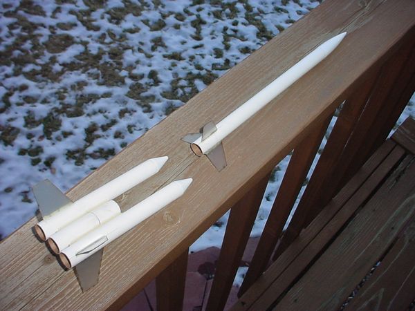
I had some down time up at our cabin, but brought some model rocket parts up with me. I made a model rocket version of the two-stage cradle boosted rocket which would use three (3) BP Estes motors for the boost (one to ignite the sustainer) instead of the two (2) HP AP motors in the larger version, with timers:
I can launch this at our next meet to see how it plays out.
Now the difference between a normal two-stage with a clustered motor booster and a cradle boosted rocket, is that the booster has a deployment system (my definition) and does not tumble down like other model rocket boosters. Consequently the center motor will be a B6-0 (to launch the sustainer) and the pods will have B6-4's (to deploy the chutes or streamers attached to the booster).
Ok that seems straight forward. If the center motor doesn't fire , but the pods do, then everything should come back attached safe and sound , assuming the top stage had a snug fit with the booster.
With more parts on hand, I thought I would take it one step further. A three-stage, double-cradle boosted rocket with all three stages having independendant deployment systems, Introducing PRIME NUMBERS (5-3-1), a 3-stage clustered cradle rocket:
The 1st stage, a 5 motor clustered booster would contain (for example) 3 B6-0's and two B6-2's. The 2nd stage 1 B6-0 and 2 B6-4's, and the 3rd stage a B6-6 (or whatever). Now this whole setup looks very racy and was a joy to build, but getting it to work right on BP motors will be one scary launch event.
Estes motors have a +/- 10% tolerance on thrust and delays so it is very possible, assuming that all 5 motors in the 1st stage fire simultaneously, that the time-to-ejection charges may wander all over the map and the 2nd and 3rd stage may depart with some motors lit before the others get a chance to fire. This is not an issue with clustered motors dumping their hot particles into a common tube or funnel to light the motors above them as any one of the lower motors could do the job. However in this case, each motor is singularly assigned to another motor. If it fails, everything above it fails as well.
I'll try flying this, but it will be a heads-up launch. Doing it with HP components should work much better, so that may be the next project after a sucessful two-stage cradle HP rocket launch.
Clip whips or flash in the pan for the first stage ignition? Either way, kool project.
Just a little more complicated than my 5 stager starting with a 4 "D" cluster. 😉 Ok a lot more complicated! In mine, if the center "D" didnt light, it would have been a much shorter ride. And no deployment. 🙄 But it all worked ok. 🙂
Also you might need little beefier moters than "B"s in the bottom. ❓
I think it looks like you have room for "D"s 🙂
Also you might need little beefier moters than "B"s in the bottom. ❓
I think it looks like you have room for "D"s 🙂
I'm just throwing out concepts, and I don't want (or want any of the helpful NCR members) to have to chase the stages very far. C's are probably a better choice for boost, but D's won't work (composites excluded) since I built it with 18mm tubes.
Looks like a beautiful machine, and it should be a blast. Any way to check the stability on it? There's lots of fins, but lots of motor weight back there, too.
Latest Post: Hello World Our newest member: jungferreira Recent Posts Unread Posts
